Introduction
Did you know that air buoyancy is a significant contributor to uncertainty in measurement results?
It affects the results of many tests and calibrations if you do not apply air buoyancy correction. Especially, measurements where a weight is involved, such as mass, force, pressure, and torque.
Many labs are not taking this into account when making measurements. Additionally, there are a lot of calibration procedures and test methods that do not include air buoyancy correction.
Ultimately, this could result in a lot of labs reporting bad measurement results in addition to understated measurement uncertainty.
At the same time, I get a lot questions related to air buoyancy and how to consider it in an uncertainty analysis. Therefore, I put this guide together to help anyone that needs to:
- evaluate the effects of air buoyancy, and/or
- apply air buoyancy correction.
In this guide, you will learn:
- What is Air Buoyancy,
- How to Calculate Air Buoyancy Correction,
- Air Buoyancy Correction Examples,
- When to Consider Air Buoyancy Correction,
- Uncertainty due to Air Buoyancy,
There is a lot great information included in this guide. So, I hope that you find it helpful.
What is Air Buoyancy
According to the Encyclopedia Britannica, buoyancy is the upward, or buoyant, force acted on an object that is completely or partially submerged in a fluid (e.g. gas or liquid) at rest; the magnitude is equal to the weight of the fluid displaced by the object.
Therefore, air buoyancy is the upward force exerted on an object by the air that is displaced by the object.
Essentially, your object (i.e. weights) are displacing air which causes them to weigh less because the air is exerting an upward force on your weights equal to the amount air they displaced.
Therefore, you must make a correction to add this amount of weight back to avoid measurement errors. Otherwise, if you do not correct for this error, then you need to consider it in your uncertainty budgets. However, it will cause you to have a larger estimate of uncertainty in measurement.
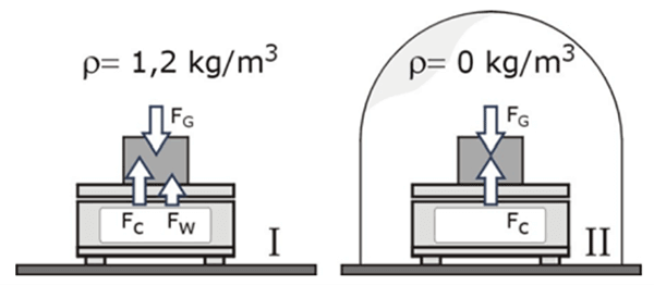
In the image below, you see a weight placed on a balance. The balance on the left is in normal conditions. The balance on the right is in a vacuum.
The weight in normal conditions (i.e. left) is affected by gravity (Fg), the reacting force (Fc), and the buoyant force (Fw).
The weight in vacuum (i.e. right) is affected by gravity (Fg) and the reacting force (Fc). Since it does not displace air, there is no need to correct it for air buoyancy.
How to Calculate Air Buoyancy Correction
Calculating air buoyancy correction is quite simple. Applying it can be more difficult depending on the application. So, let’s learn how to calculate air buoyancy correction first, then we can look at a few examples that show how to apply it to your measurements.
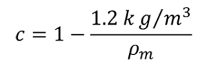
Look at the equation below. It is the basic equation for correcting for air buoyancy.
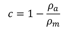
Where,
c = correction factor
ρa = air density
ρm = mass density
To calculate air buoyancy, you will need to follow the 3 steps listed below:
- Find the Air Density
- Find the Mass Density
- Calculate Air Buoyancy Correction
1. Find the Air Density
The first thing you need to calculate air buoyancy correction is find the air density. Most people assume that air density is 1.2 kg/m3. However, that is not always the case. It really depends on your location and your environmental conditions.
For example, a lab at higher elevations will have a hard time having an air density of 1.2 kg/m3.
Make sure you calculate your own air density instead of using the default 1.2 kg/m3.
Air density is affected by the following factors:
- Air Temperature,
- Barometric Pressure, and
- Relative Humidity.
With this information, you can easily calculate your air density.
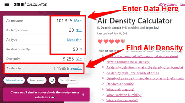
The easiest way to find this information is with this air density calculator. It is great for finding what you need quickly.
I recommend using the Omni Air Density Calculator. It is the calculator that I use most of the time.
Plus, it is the only online calculator that I have found to calculate the density of moist air.
You can see what it looks like in the image below.
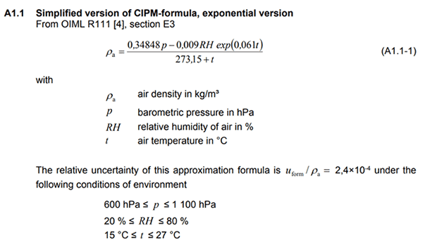
If you do not trust online calculators, you can use the simplified CIPM formula for calculating air density. To learn more about the CIPM formula check out this journal article from Metrologia or the EURAMET CG-18.
Metrologia
Revised formula for the density of moist air (CIPM-2007)
Euramet CG-18
Guidelines on the Calibration of Non-Automatic Weighing Instruments
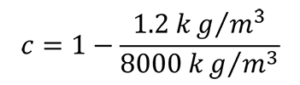
To save you time, look at the image below to see the simplified CIPM formula.
2. Find the Mass Density
After determining your air density, the next step you want to complete is find your mass density. Finding the mass density of your standard weights should be easy. Typically, you can find this information from:
- Manufacturer specifications, or
- Your calibration reports.
Manufacturer Specifications
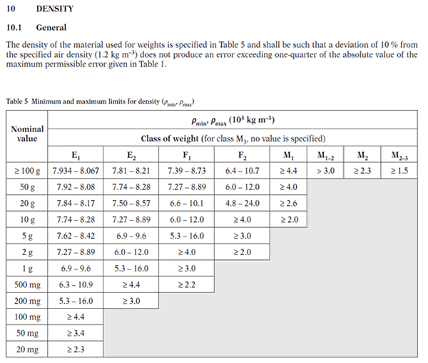
In the image below, you will see a table from the OIML R111 that provides requirements for mass density based on the mass value and class.
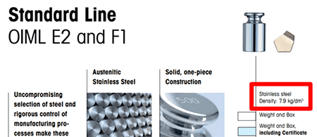
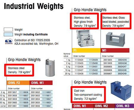
Next, look at the images below. These images were sourced from a weight manufacturer’s brochure and catalog.
You will see that it is easy to find the mass density for your type of weight.
In the image below, you will find the mass density given for both OIML and ASTM class weights. This was easily found in the weight manufacturer’s catalog.
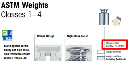
In the next image, you will see more mass density values given for industrial weights. Again, these were easily found in the weight manufacturer’s catalog.
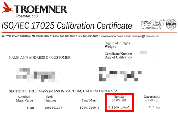
Calibration Reports
However, if you want the best approximation of your weight’s mass density, look at your calibration reports. Especially, if they are from the OEM. Typically, weight manufacturers provide a more accurate value for mass density.
Look at the image below to see the mass density provided in this calibration report.
3. Calculate Air Buoyancy Correction Factor
Now that you have both your air and mass density values, you can use the formula below to calculate air buoyancy correction. Just follow the steps listed below:
1. Replace ρa with your value of air density,
2. Replace ρm with your value of mass density,
3. Divide air density by the mass density,
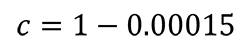
4. Subtract the result of step 3 from one (i.e. 1),
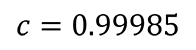
The result will be your air buoyancy correction factor. You will use it to correct your mass, force, and torque measurement results.
In the next section, you will see examples with formulas for making corrections due to air buoyancy.
Air Buoyancy Correction Examples
In this section, you will see examples of common measurement functions that require air buoyancy correction.
Mass Measurements
According to NIST SOP-2 (which is part of NISTIR 6969 ), air buoyancy is one the largest sources of uncertainty when calibrating standard mass and weights.
Look at the equation below to see the formula used to calculate air buoyancy correction for mass measurements.
From NIST SOP-2
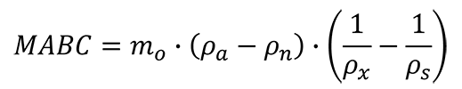
Where,
MABC = magnitude of air buoyancy correction
mo = nominal mass
ρa = air density at the time of measurement
ρn = density of “normal” air
ρx = density of unknown weight
ρs = density of reference standard
Next, is the formula for calculating the mass of an unknown weight per NIST SOP-2. Notice that the equation takes in account air buoyancy correction.
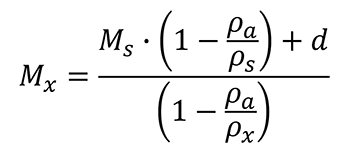
Where,
Mx = mass of unknown weight
Ms = mass of reference standard
d = difference between the unknown weight and the reference standard
ρa = air density at the time of measurement
ρn = density of “normal” air
ρx = density of unknown weight
ρs = density of reference standard
Scale and Balance Calibrations
Calibrating scales requires you to make corrections for local gravity and air buoyancy.
Look at the equation below to see the formula recommended by the EURAMET CG18 for calibrating scales and balances.
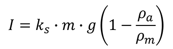
I = indication
M = mass
G = local gravity acceleration
ρa = air density
ρm = mass density
Ks = adjustment factor
Force Measurements using Dead Weight
Calibrating force instruments with dead weight requires a correction for air buoyancy.
Look at the equation below to see how to correct your force measurements for air buoyancy.
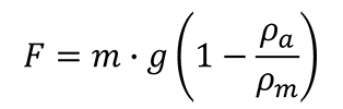
F = force
m = mass
g = local gravity acceleration
ρa = air density
ρm = mass density
Pressure measurements using Deadweight Testers
Performing pressure calibrations with a dead weight tester requires the need to make corrections for air buoyancy (except when you generate absolute pressure with a vacuum reference).
Look at the equation below to see the deadweight tester formula. Pay attention to the air buoyancy correction formula.
Pneumatic Pressure
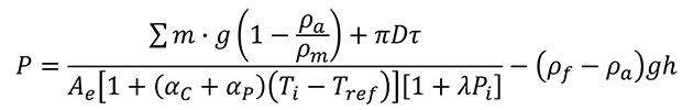
P = Pressure
m = mass
g = local gravity acceleration
ρa = air density
ρm = mass density
D = diameter of piston
τ = surface tension of fluid
Ae = effective area of the piston
αc = thermal expansion coefficient of the piston cylinder
αp = thermal expansion coefficient of the piston
Ti = temperature (at the time of test)
Tref = reference temperature
Pi = nominal or target pressure
ρf = fluid density (i.e. N2)
h = height from reference
Hydraulic Pressure
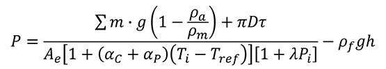
P = Pressure
m = mass
g = local gravity acceleration
ρa = air density
ρm = mass density
D = diameter of piston
τ = surface tension of fluid
Ae = effective area of the piston
αc = thermal expansion coefficient of the piston cylinder
αp = thermal expansion coefficient of the piston
Ti = temperature (at the time of test)
Tref = reference temperature
Pi = nominal or target pressure
ρf = fluid density
h = height from reference
Torque Measurements using Dead Weight
Performing static torque calibrations requires the use of a torque wheel or arm, cable, pan, and weights to generate a desired amount of torque.
Since dead weight is used, you need to make corrections for air buoyancy.
Look at the equation below to see the formula used to calibrate torque transducers.
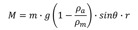
M = Moment of force (i.e. Torque)
m = mass
g = local gravity acceleration
ρa = air density
ρm = mass density
θ = angle of applied force
r = radius of wheel or length of arm/lever
As you can see, there are plenty of examples for correcting measurements for air buoyancy.
When to Consider Air Buoyancy Correction
The effects of air buoyancy can significantly affect your measurement results. Here is when you should consider it in your uncertainty analysis:
1. When it affects your measurement results
Before you include air buoyancy in your uncertainty analysis, make sure that it affects your measurement process and results. Typically, you will find this factor affects the following type of measurements:
- Mass measurement,
- Scale and balance calibration,
- Force measurement (with dead weight),
- Pressure measurement (with Deadweight Testers), and
- Torque measurement (with dead weight)
The key here is each of these measurements has mass or weights that are displacing air.
So, ask yourself this simple question; “Does it displace air?”
- If the answer is Yes, consider it in your uncertainty analysis.
- If the answer is No, don’t consider it in your uncertainty analysis.
2. When you have variations in air density
Air buoyancy can cause uncertainty in your measurement results when there is a change in air density. Since you are most likely dealing with moist air, your air density can be affected by the follow factors:
- Temperature,
- Pressure, and
- Humidity
Here is a link to one of my favorite online calculators for determining the density of moist air:
Also, you can use the simplified CIPM formula for calculating air density. To save you time (needed to look it up), look at the image below to see the formula.
3. When you have variations in mass density
Uncertainty in mass density is often overlooked. Many labs do not consider it in their uncertainty budgets, and many manufacturers do not list it in their specifications or calibration reports.
Do you think that every stainless-steel weight actually has an exact density of 8000 kg/m3?
The answer is: Probably not.
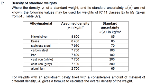
Luckily, the EURAMET CG-18 is available to help. In Appendix E of the guide, you will find the table shown below. It provides the standard uncertainty in mass density for common standard weight materials.
This is really helpful information since it is hard to find.
Look at the table below to find the uncertainty in mass density based on the material of the standard weight.
Uncertainty due to Air Buoyancy
Air buoyancy can affect measurement results due to:
- Changes in air density, and/or
- Differences in density between calibration and use.
Changes in Air Density
Air density is affected by the following environmental factors:
- atmospheric pressure,
- temperature, and
- humidity.
When any of these variables change it causes a change in air density. This change can affect your measurement results and increase your uncertainty.
Difference Between Conditions: Calibration vs Use
The differences in air density between the time your equipment was calibrated and the time your equipment is used can cause uncertainty in measurement results.
For example, the Euramet CG-18 recommends an adjustment factor to correct the conventional mass value of your standard weights when the air density at the time of use does not match the reference air density (approximately 1.2 kg/m3).
Conclusion
Air buoyancy can be a significant contributor to uncertainty in measurement results; especially when you deal with measurement functions that involve weight (e.g. mass, pressure, force, torque).
In this guide, you should have learned:
- What is air buoyancy?
- How to calculate air buoyancy,
- When to consider air buoyancy correction, and
- How air buoyancy affects measurement uncertainty.
Plus, this guide has provided plenty of common measurement examples so you can confidently correct your measurement results for air buoyancy.
Make sure to take air buoyancy into account when reporting measurement results or be sure to include it in your uncertainty analysis. Correcting measurement results for air buoyancy should yield you a smaller uncertainty. If you do not correct your measurement results for it, then you will need to include it in your uncertainty analysis which will yield you a larger uncertainty.
The choice is up to you.